Pi 4 Model B Rev 1.5 - Test Points
Board Image
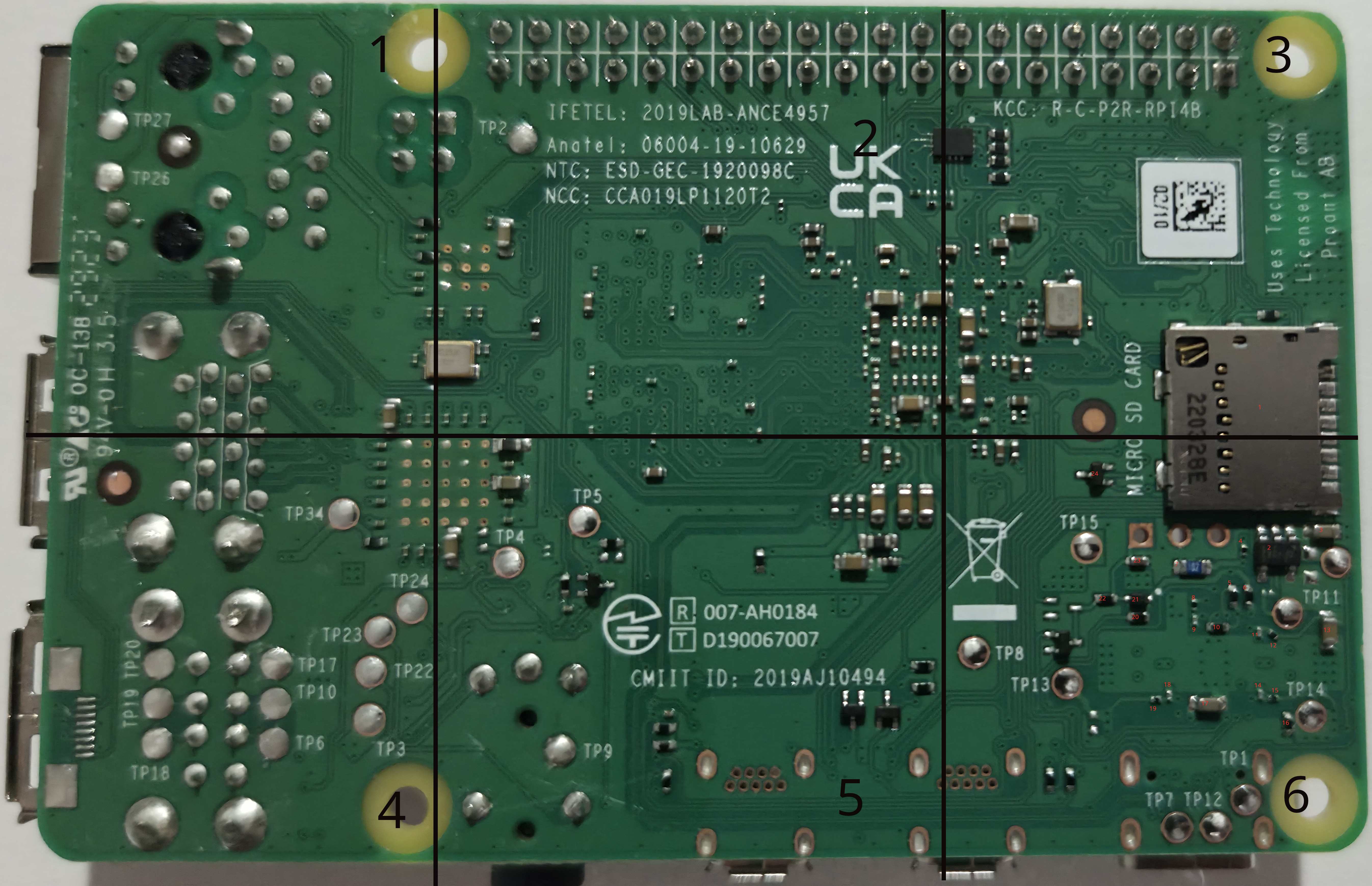
Readings
Powered- These measurements were taken with the board plugged in/powered on, and nothing else plugged in including no SD Card insertedOS Idle- These measurements were taken with the board booted into Raspberry PI OS. These tests are different from Power Only in that the SD card is inserted and we have booted from it.Resistance- These measurements were taken without power. This is a measurement of resistance to ground from the given test point.
| Test Point | Zone | Powered | OS Idle | Resistance |
|---|---|---|---|---|
| TP1 | 6 | 5.45v | 5.47v | 2k |
| TP2 | 2 | 5.44v | 5.47v | 2k |
| TP3 | 4 | 5.44v | 5.47v | 2k |
| TP4 | 5 | 0v | 3.32v | 75k |
| TP5 | 5 | 3.32v | 3.32v | 3.4k |
| TP6 | 4 | 0v | 0v | OL |
| TP7 | 6 | 0v | 0v | 0.2 Ω |
| TP8 | 6 | 0v | 0v | 0.2 Ω |
| TP9 | 5 | 0v | 0v | 0.2 Ω |
| TP10 | 4 | 0v | 0v | OL |
TP11a* |
6 | 3.32v | 3.32v | 1.6k Ω |
TP11b* |
6 | 3.32v | 3.32v | 48m |
| TP12 | 6 | 0v | 0v | 0.2 Ω |
| TP13 | 6 | 1.80v | 1.80v | 8.6k |
| TP14 | 6 | 1.10v | 1.10v | 90 Ω |
| TP15 | 6 | 1.00v | 0.87v | 44.4 Ω |
| TP16 | ||||
| TP17 | 4 | 0v | 0v | 0.2 Ω |
| TP18 | 4 | 0v | 0v | OL |
| TP19 | 4 | 0v | 0v | OL |
| TP20 | 4 | 0v | 0v | 0.2 Ω |
| TP21 | ||||
| TP22 | 4 | 0v | 0v | 1.8k Ω |
| TP23 | 4 | 0v | 0v | 1.8k Ω |
| TP24 | 4 | 0.52v | 0.52v | 75 Ω |
| TP25 | ||||
| TP26 | 1 | 3.32v | 3.33v | OL |
| TP27 | 1 | 3.32v | 3.33v | OL |
| TP28 | ||||
| TP29 | ||||
| TP30 | ||||
| TP31 | ||||
| TP32 | ||||
| TP33 | ||||
| TP34 | 4 | 1.03v | 1.03v | 53 Ω |
* - There are two points near TP11, one is not numbered. Presumably
TP11 is the one further from the SD card slot. As such in this diagram
a is the one farther from the SD slot and b is the one closer to the
SD slot and closer to the edge of the board.